How to Prepare a DXF File for Laser Cutting: A Practical Guide
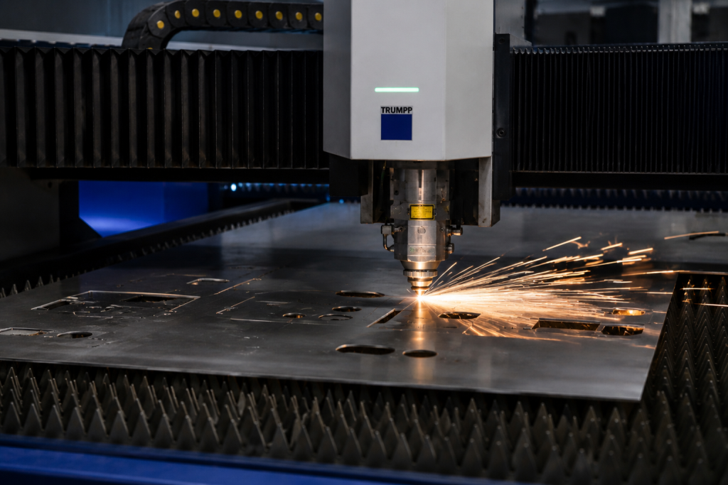
If you’ve ever submitted a file for laser cutting and been told it can’t be cut as-is, you’re not alone. It happens constantly, and it almost always comes down to the same handful of issues: open paths, wrong units, duplicate lines, or unnecessary elements that confuse the cutting software. The good news is that all of these are easy to fix once you know what to look for. At 1Laser in Kempton Park, we work with DXF files every single day. We’ve seen the full range, from perfectly prepared files that go straight into production, to files that need significant rework before we can even nest them. This guide exists to help you land firmly in the first category, get your parts cut accurately and on time, and avoid the back-and-forth that slows everything down. What Is a DXF File and Why Does Laser Cutting Require One? DXF stands for Drawing Exchange Format. It’s a 2D vector file format originally developed by Autodesk as a way to share drawing data between different CAD programs. In laser cutting, it’s the standard format because it describes geometry, lines, arcs, curves, and shapes using mathematical data rather than pixels. That matters enormously for precision work. Unlike a JPG or PNG image, a DXF file doesn’t lose resolution when scaled. The laser cutting software reads the geometry directly from the file and translates it into cutting instructions for the machine. What you draw is exactly what gets cut, which is why getting the file right before submission is so important. What Software Can You Use to Create a DXF File? You don’t need to be an engineer or own expensive software to produce a usable DXF file. Here are the most common options, from professional CAD tools to free alternatives. AutoCAD is the industry standard for technical drawing and produces extremely clean DXF exports. If you’re working in a professional or engineering environment, this is likely already what you’re using. Fusion 360 by Autodesk is a powerful 3D CAD and CAM tool with a free tier for personal and small business use. You can model your part in 3D and then export a flat DXF of the face you want cut. It’s excellent for precision parts. SolidWorks is widely used in manufacturing and engineering environments and exports clean, accurate DXF files from flat sheet bodies and sketches. Inkscape is a free, open-source vector graphics tool that works well for decorative or artistic laser cutting projects. It’s not a CAD program, so it’s better suited to flat designs, signage, and décor than to precision engineering parts. It exports DXF and is perfectly usable for 1Laser’s process. CorelDRAW and Adobe Illustrator are graphic design tools that can export DXF files and are commonly used for signage, decorative metalwork, and artistic cut profiles. If you don’t have access to any of these or aren’t comfortable creating your own file, 1Laser offers a CAD and design service. Send through your sketch, dimensions, or idea and the team will produce a production-ready DXF for you. The Golden Rules of a Good DXF File Before getting into the detail, here are the non-negotiable requirements that every DXF file submitted for laser cutting must meet. 1:1 scale in millimetres. Your file must be drawn at actual size. If your finished part needs to be 150mm wide, the drawing must be 150mm wide. Not 150 inches, not 15cm in a different unit system. Millimetres, actual size, always. When in doubt, double-check your software’s units before exporting. All paths must be closed. A closed path is one where every line and curve connects perfectly to the next, forming a complete, unbroken outline. Open paths, where the start and end points don’t meet, or where two lines appear to connect but don’t quite touch at the vertex, cause errors in the cutting software. The machine doesn’t know where to start or stop cutting, and the result is either a rejected file or a mis-cut part. One line per edge. Duplicate or overlapping lines are one of the most common file errors. They look fine on screen because they sit exactly on top of each other, but the cutting software reads them as two separate cut paths, which means the laser passes over the same line twice. This wastes time, can damage your material, and affects edge quality. Most CAD programs have a tool to detect and remove duplicates. In AutoCAD it’s called OVERKILL. Use it before every export. No extra elements. Your DXF should contain only the cut profiles and nothing else. No dimensions, no annotations, no title blocks, no construction lines, no text, no hatching. All of these need to be deleted or moved to a non-cutting layer before you export. The laser cutting software will attempt to cut everything it finds in the file, and that includes your dimension lines and labels. Minimum hole sizes. As a general rule, the diameter of any hole you want cut should be at least equal to the material thickness for steel up to 4mm. For thicker material, a minimum diameter of 1.5 times the material thickness is a safer guideline. Holes smaller than this are difficult to cut cleanly and may not be achievable on thinner, more delicate materials. Step by Step: Preparing Your File for Submission Here’s the practical process to follow before you submit your DXF to 1Laser. Step 1: Draw or import your design at 1:1 scale Set your document units to millimetres before you start drawing. If you’re working from an imported sketch or image, trace it carefully using vector tools rather than embedding the raster image into the file. Everything in the final DXF must be vector geometry, not a linked or embedded image. Step 2: Check all paths are closed Go through each profile in your drawing and verify that every outline is a closed, continuous path. In Inkscape you can select a path and check its properties. In AutoCAD and Fusion 360, use the PEDIT or Join